
Within an integration system, applications rarely exchange data using exactly the same structure. An API may produce an order in JSON format, while an ERP expects a document with different property names, a different structure, or calculated values.
Azure provides several mechanisms for manipulating and transforming messages. The choice of tool depends primarily on the nature of the processing to be performed.
The Data Mapper is a design tool available in Visual Studio Code with the Azure Logic Apps (Standard) extension: https://marketplace.visualstudio.com/items?itemName=ms-azuretools.vscode-azurelogicapps.
It allows you to model a transformation between the properties of a source schema and those of a target schema. To do this, elements are visually connected to each other through a graphical mapping interface. Functions can also be inserted between these elements to perform operations such as:
When the mapping is saved, the tool generates an XSLT transformation file that will be executed by the Logic Apps runtime. This tool therefore provides a graphical interface for building XSLT transformations without having to manually write the entire code.
Several Logic Apps features may seem similar, but they address different needs.
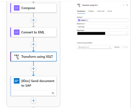
Data Operations actions, such as Select, Compose, Filter array, or Parse JSON, are suitable for relatively simple manipulations performed directly within a workflow.
The Data Mapper becomes more useful when:
In this article, we will explore the Transform using Data Mapper XSLT action, designed for mappings created with the Data Mapper. It should not be confused with the Transform XML action, which is intended for XSLT transformations created with other tools.
This distinction is important: a mapping generated by the Data Mapper must be called using the action dedicated to Data Mapper operations.
To create a mapping, you need:
Schemas can be provided as:
In the rest of this article, we will use two XSD files to illustrate a more advanced XML transformation.
Officially, Microsoft states that the Data Mapper is supported in Visual Studio Code on Windows only. However, on macOS, it is possible to use the graphical editor to create and modify mappings through workarounds.
However, the native Test Map feature available on Windows does not work natively on macOS because it depends on a Windows-specific .NET Framework component. It is still possible to test transformations locally using the Logic Apps testing SDK and .NET tests.
For more details, see: Workaround: Testing Logic Apps Data Mapper Maps on macOS – DEV Community
To illustrate the Data Mapper with a more realistic use case, let’s take the example of a company called MyCompany. This company receives e-commerce orders in XML format and needs to transform them into a format expected by its ERP.
The source flow contains the following data:
However, MyCompany‘s ERP expects a different format, structured as follows:
In our case, the solution therefore consists of using a Logic App Standard with the Data Mapper to transform the source format into the target format.
Why use the Data Mapper here? Because it is not limited to connecting simple fields. It can also handle nested structures, collections, value conversions, calculations, and conditional rules.
The transformation must therefore perform several mapping operations. In the Data Mapper tool, these transformation rules are represented graphically by connections between source and target nodes, using intermediate functions where necessary.
How to: Create Standard Workflows with Visual Studio Code – Azure Logic Apps | Microsoft Learn
https://learn.microsoft.com/en-us/azure/logic-apps/create-standard-workflows-visual-studio-code
The first step is to add the XSD data schemas that we are going to use.
These schemas will then be used by the Data Mapper to display the structure of the source message and that of the target message. They will make it possible to create mappings between the different XML elements.
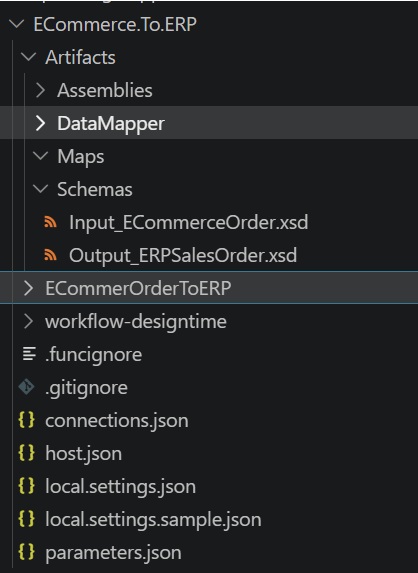
In Visual Studio Code, open the Logic Apps Standard project, then go to the Data Mapper section of the Azure extension.
It is also possible to create a map from the workspace “Explorer” view. To do this, right-click the “Maps” folder, then select “Create Data Map”.
After entering the name of our new map, a Data Map creation interface will open. This interface mainly consists of three areas:
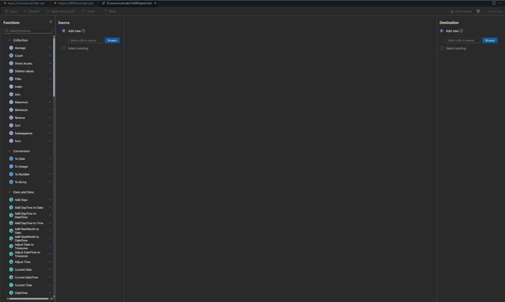
Before we can apply our transformation rules, we need to specify the source and target schemas. Once this is done, you should find all the properties under “Source” and “Destination”:
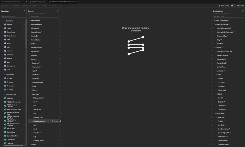
On the left side of the interface, we find the list of functions provided by the Data Mapper. These functions can be used to build more complex transformations, such as concatenations, calculations, conditions, or value conversions.
Once the schemas are loaded, we can start creating the first mappings between source and target fields.
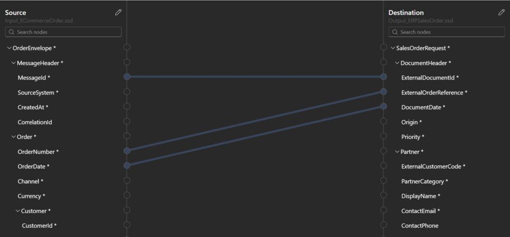
When no transformation is required, a source element can be directly connected to a target element. This type of mapping is suitable when both elements use compatible types.
To do this, select the source property, then draw a connection to the target property using drag and drop.
Here is the result with other direct mappings:
The Data Mapper provides several types of functions. These include functions for performing conversions, manipulating arrays, applying conditions, or processing strings.
For example, let’s imagine that we have the following mapping rules:
| Source | Target | Mapping |
|---|---|---|
| Order.Customer.Type | Partner.PartnerCategory | Conversion B2C → CONSUMER, B2B → BUSINESS |
| Order.Customer.FirstName + Order.Customer.LastName | Partner.DisplayName | Concatenation for an individual customer |
| Order.Customer.CompanyName | Partner.DisplayName | Used if the customer is of type B2B |
The result could look like this:
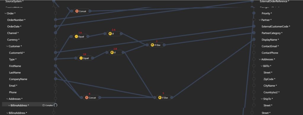
With:
Using functions makes it possible to keep transformation logic within the mapping rather than multiplying intermediate actions in the workflow.
To transform lines into items, the parent elements of both arrays must be connected.
The Data Mapper then adds the required iteration logic. However, the internal properties still need to be explicitly mapped.
For example, we want to create a mapping to OrderLines.OrderLine.LineAmount:
| Source | Target | Mapping |
|---|---|---|
| Lines.Line.QuantityLines.Line.UnitPriceLines.Line.DiscountAmount | OrderLines.OrderLine.LineNetAmount | Lines.Line.Quantity x Lines.Line.UnitPrice – Lines.Line.DiscountAmount |
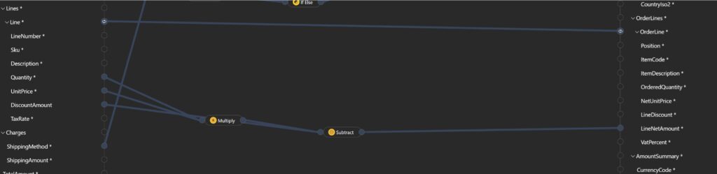
A connection is automatically created between the parent elements of the collection.
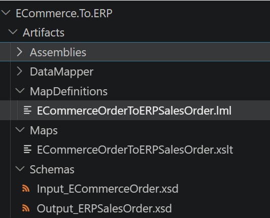
When saving, the Data Mapper creates two main artifacts:
The .lml file contains the definition used by the visual editor.
The .xslt file contains the transformation executable by Logic Apps.
Both files must be kept in the Git repository. The .lml file makes it possible to continue visually editing the mapping, while the .xslt file is the artifact used at runtime. Schemas can also be stored in the following folder: Artifacts/Schemas.
This organization makes it easier to manage contracts and mappings within the same project as the workflows.
Thanks to the Azure Logic Apps (Standard) extension, it is possible to test a map directly from Visual Studio Code. The Data Mapper includes a test panel where you can provide a sample source message.
Warning: before running the test, the mapping must be saved in order to regenerate the XSLT file with the latest changes.
The transformation result is then displayed directly in Visual Studio Code. This feature makes it possible to quickly test:
If an error occurs during testing, you should check the input XML message, the validity of the XSD schemas, and the local Logic Apps Standard runtime configuration.
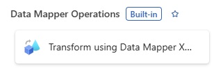
Once the mapping has been saved, it can be called from the workflow designer. Add the built-in Transform using Data Mapper XSLT action.
The action mainly requires:
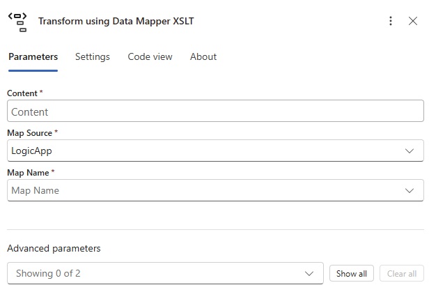
In a local project, simply select the file located in the Artifacts/Maps folder.
The result of this action can then be passed to the next steps in the workflow, for example to a Service Bus topic.
In a Logic App Standard, local artifacts can be deployed with the application and its workflows.
For a deployment using a YAML pipeline, the Logic App Standard project is first packaged as a ZIP archive and then published as a pipeline artifact. This archive contains the elements required by the map, including the .lml, .xslt, and schema files.
Here is a code example:
- task: AzureLogicAppsStandardBuild@1
  displayName: 'Azure Logic Apps Standard Build'
  inputs:
    sourceFolder: '$(Build.SourcesDirectory)/MyLAppStd.ProjectName/MyLAppStdName'
    deploymentFolder: '$(System.DefaultWorkingDirectory)/deployment/MyLAppStd.ProjectName/'
    archiveFile: '$(Build.ArtifactStagingDirectory)/$(Build.BuildId).zip'
    deploymentWorkflowParametersFile: '$(Build.SourcesDirectory)/MyLAppStd.ProjectName/MyLAppStd.ProjectName/parameters.json'
- task: PublishPipelineArtifact@1
  displayName: 'Publish logic app zip artifact'
  inputs:
    targetPath: '$(Build.ArtifactStagingDirectory)/$(Build.BuildId).zip'
    artifact: 'MyArtifactName'
    publishLocation: 'pipeline'
Deploying a Logic App Standard is done in two steps:
The code can be deployed once the project has been built and the artifact published. The ZIP archive can then be deployed to the target resource.
Here is a code example showing how to do this:
- job: Deployment_LogicApp
  displayName: "Deploy Logic App"
  steps:
    - task: DownloadPipelineArtifact@2
      displayName: "Download LogicApp Artifact"
      inputs:
        artifact: 'MyArtifactName'
        path: $(Pipeline.Workspace)
    - task: AzureFunctionApp@1
      displayName: "Deploy logic app workflows"
      inputs:
        azureSubscription: "MyAZureSubscription"
        appType: "functionAppLinux"
        appName: "my-lapp-std-dev"
        package: "$(Pipeline.Workspace)/MyArtifactName"
        deploymentMethod: "zipDeploy"
Ultimately, using the Data Mapper does not add any specific deployment step. However, it adds artifacts that must be included in the Logic App Standard package.
Schema files, .lml files, and .xslt files must be placed under source control.
A schema modification can have a direct impact on multiple mappings. These changes should therefore be treated as interface contract evolutions.
When the transformation is managed with the Data Mapper, it is preferable to modify the .lml file from the visual editor and then regenerate the XSLT.
A manual modification to the generated file may be lost the next time the mapping is saved.
For more specific requirements, the Data Mapper makes it possible to integrate XSLT fragments or use custom functions.
At the time of writing this article, several limitations need to be taken into account:
These limitations do not call into question the value of the tool, but they should be considered before choosing the Data Mapper for a complex transformation.
The Data Mapper brings a visual transformation experience to Azure Logic Apps Standard that is particularly useful for structured integration scenarios.
It makes it possible to separate conversion rules from orchestration, work from schemas, test transformations locally, and version artifacts alongside the rest of the project, which is also an advantage.
It is particularly well suited to teams working with complex XML or JSON contracts, but can also be used when modernizing an integration platform based on BizTalk Server, for example.
For simple transformations, Data Operations actions often remain sufficient. However, when message structures become complex or when the mapping represents a true integration contract, the Data Mapper provides a more readable, testable, and maintainable solution.
